My Project of Cloning Pong:
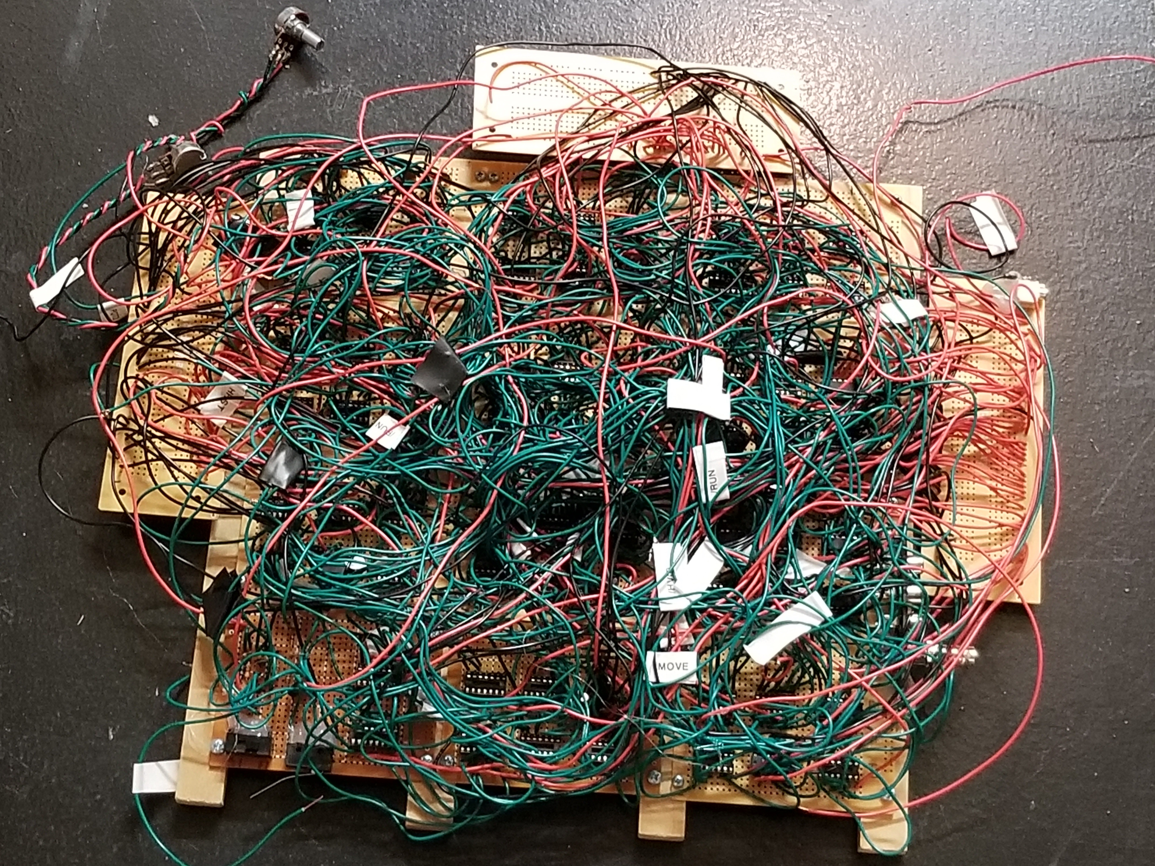
This is a true digital rats' nest. :)
Back when I was 11, I wanted to buy some arcade games off Ebay. My parents told me they didn't want me to do that. I asked them if they would be okay with me buying the TTL logic chips and wiring up Pong myself. They were okay with that. So, over the next few months I saved up to buy all of the logic chips.
When the logic chips arrived, I started to clone Pong using these schematics redrawn by Dan B. I have noticed that some parts in the paddle circuits are wrong, so be sure to verify against the originals.
I finished wiring it up but could not solve all of the issues. These included:
- The score was being repeated all over the screen.
- Each player had ~16 paddles. (There were around 32 on the screen...)
- Paddles would stretch to the bottom of the screen.
- The clock circuit would crash when the ball would hit a paddle.
- Game would not coin up.
Here are some thoughts as to what caused most of the problems:
For problem 1: I learned there is a big difference between a 744852 and a 7448. One is CMOS, one is TTL, and both do completely different things.
For problem 2: I think I bridged 4H with something...
For problem 3: I think something degraded in the paddle circuits, because it wasn't always this way.
For problem 4: I must have bridged something with the clock signal.
For problem 5: I probably soldered something into the wrong position.
I also made some other mistakes: I used a SPDT switch instead of a DPDT switch for the Max Score / Game setting, and I routinely bridged connections while soldering.
Other things about the project:
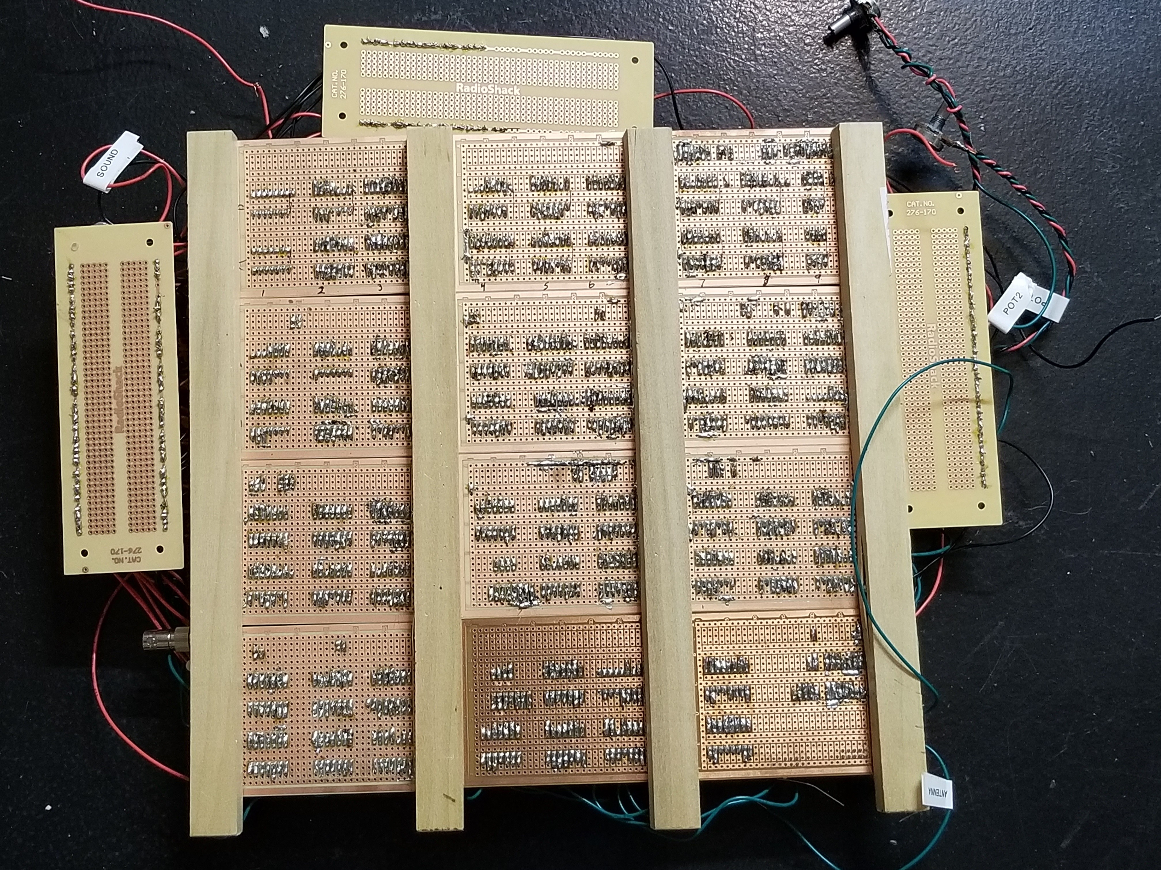
I used over 300 feet of wire. (In 30-foot spools!)
We cleaned several Radio Shacks out of those perfboards and spools of wire.
We probably ended up spending over $300 to do it just because of the prices of perfboards and wire at Radio Shack. After I showed them my level of commitment to the project by saving for more than half a year to purchase the required logic chips, and then I realized I didn't have money for perfboards and wire, my parents stepped in and paid for the rest.
This was before I knew that μf and mfd on a capacitor both meant microfarad. At the time, I searched for capacitors that said mfd and μf since I thought the difference mattered. I think one of the capacitors cost $50 because it said mfd.
I also had recently gotten a label maker so I used it to label major signals.
Some old pictures I found:
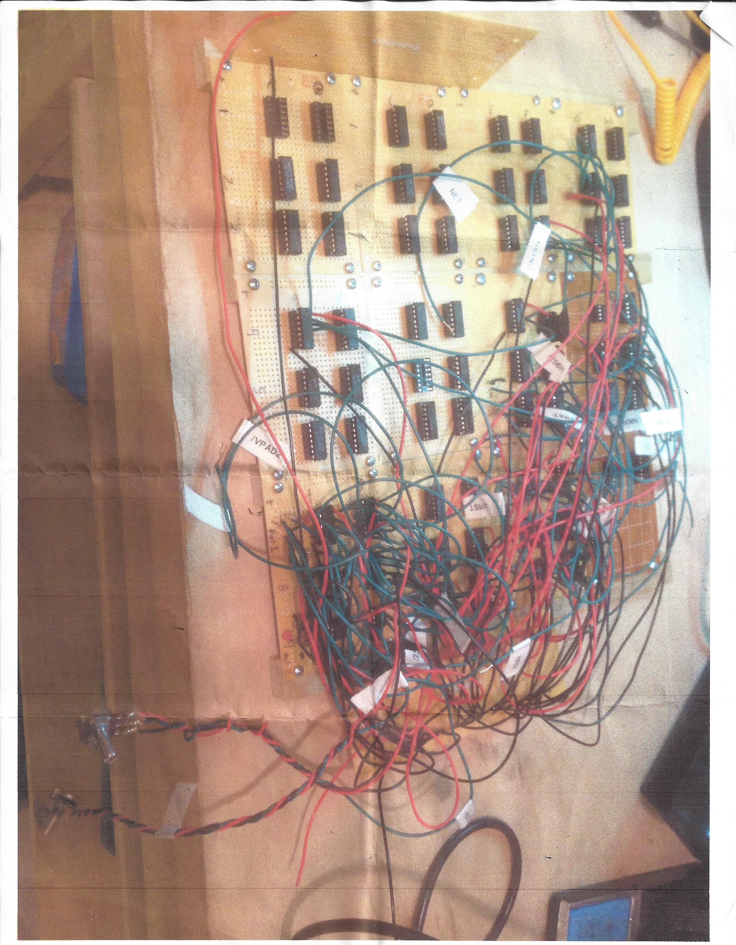
This was pretty early into the project. I was only continuing with circuits once I was confident I was getting something that looked good on the 'scope.
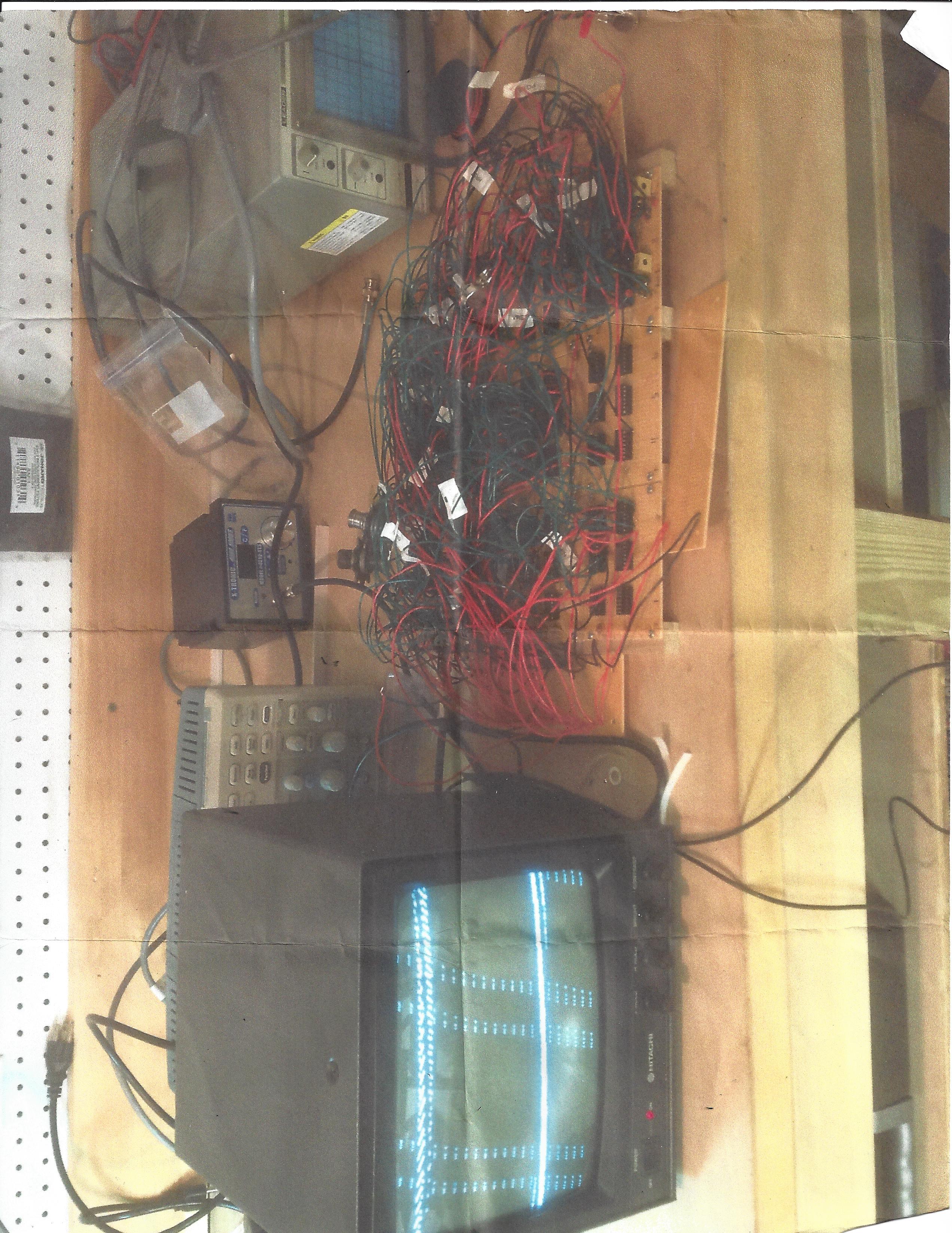
I had soldered up several video circuits before actually seeing what it looked like on the monitor. I had the paddles and the net. After seeing this on the screen, I learned that the MHZ of a crystal matters. A 16MHZ crystal in will make things happen too fast, and will prevent the monitor from being able to lock on to the sync signal. A 14.31818 MHZ crystal made the paddles and net appear. Exciting!
Obviously, these pictures were printed awhile back and scanned. I don't know what happened to any other pictures I might have had, but they're probably long gone.
This page was last updated 1/5/2022
Spelling, grammar, and readability corrections.
This page was likely written sometime during summer break in 2019.